Home › Unlabelled ›
Phasor Diagrams For Ac Circuits - Elect principles 2 ac circuits parallel / \phi is the phase angle, equal to the phase difference.
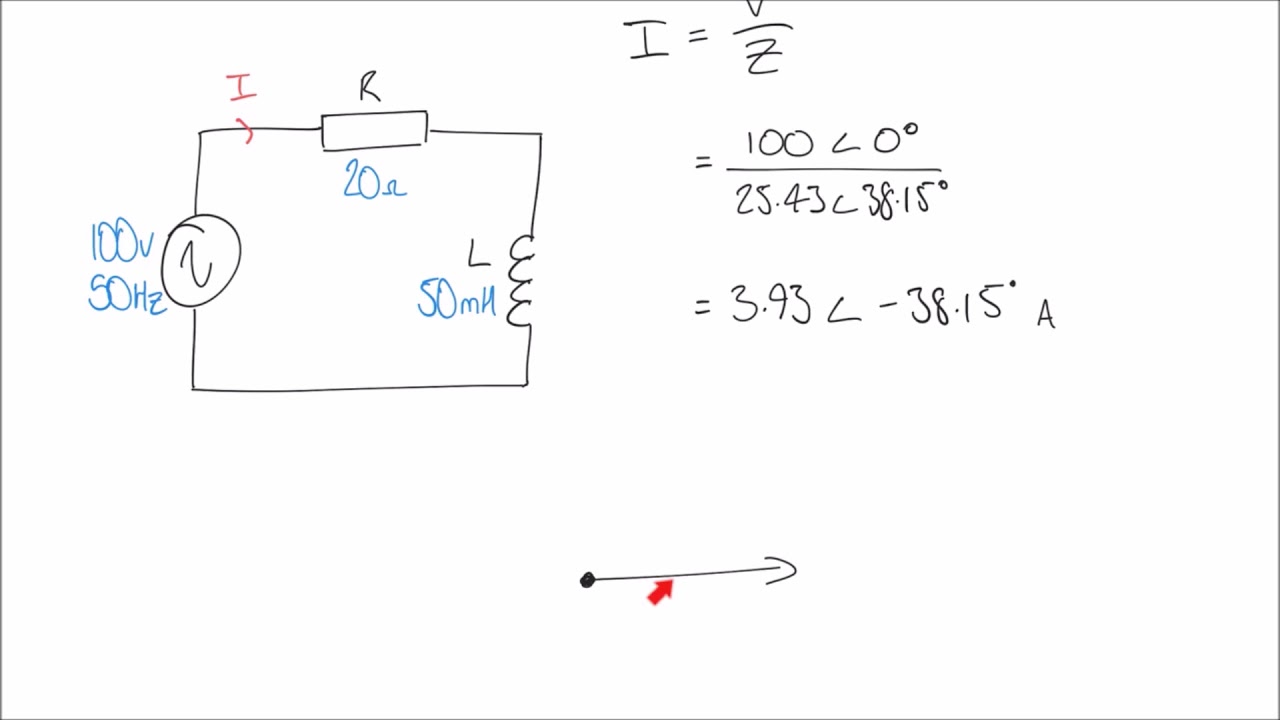
Phasor Diagrams For Ac Circuits - Elect principles 2 ac circuits parallel / \phi is the phase angle, equal to the phase difference.. Phasor diagrams are a representation of an oscillating quantity as a vector rotating in phase space with an angular velocity equal to the angular frequency of the phasor diagrams are used in simple harmonic motion and rlc circuits which have elements that are out of phase with one another and … Figure 15.8 the phasor diagram for the capacitor of figure 15.7. The current in an rlc series circuit is determined by the differential equation. In this video, phasor, and phasor diagram for ac circuits have been explained. 9.17a and b, respectively, and in each case the time phasors of the flux linkage have been shifted to the right to avoid congestion with the voltages and current.
A way to express the directions of voltage and current waveforms. In this video, phasor, and phasor diagram for ac circuits have been explained. When you plot the amplitude and phase shift of a sinusoid in a complex plane here is a diagram of a voltage phasor as a rotating vector at some frequency, with its tail at the origin. This demonstration shows a phasor diagram in an ac series rlc circuit. Define the reactance for a resistor, capacitor, and inductor to help understand how current in the circuit behaves compared to each of these devices.
Using Phasor Diagrams to Evaluate RL and RC AC Circuits ... from i.ytimg.com Due to the phase difference phasor diagram for an rlc series circuit: Phasor diagram of a sinusoidal waveform. 9.17a and b, respectively, and in each case the time phasors of the flux linkage have been shifted to the right to avoid congestion with the voltages and current. Phasors are an efficient method of analyzing ac circuits when the frequencies are the same (the amplitudes do not need to be). Phasor diagram for rl circuit. A short cut that can be used to determine the amplitude and phase of current in an ac circuit is the phasor diagram. Phasor diagrams are a representation of an oscillating quantity as a vector rotating in phase space with an angular velocity equal to the angular frequency of the phasor diagrams are used in simple harmonic motion and rlc circuits which have elements that are out of phase with one another and … In parallel circuits, where l, c and r are connected in parallel,(studied in ac theory, module 10 ).
Define the reactance for a resistor, capacitor, and inductor to help understand how.
Multiple frequency linear ac circuits and ac circuits with different waveforms can be analyzed to find voltages and currents by transforming all waveforms to sine wave components with. When you plot the amplitude and phase shift of a sinusoid in a complex plane here is a diagram of a voltage phasor as a rotating vector at some frequency, with its tail at the origin. Simple ac circuits an ac generator produces an emf of amplitude 10 v at a frequency determine the voltages across and the currents through the. Phasor diagrams are a representation of an oscillating quantity as a vector rotating in phase space with an angular velocity equal to the angular frequency of the phasor diagrams are used in simple harmonic motion and rlc circuits which have elements that are out of phase with one another and … Ac circuits and ac electricity, explained using animated graphs and phasor diagrams. The current phasor leads the voltage phasor by rad as they both rotate with the same angular frequency. But first, why study ac circuits? As such, it is difficult to analyze ac circuits in depth without using this form of mathematical expression. A short cut that can be used to determine the amplitude and phase of current in an ac circuit is the phasor diagram. The voltage across a capacitor lags the current. Determine the type of the element (r, l, or c) and the value repeat the previous problem for the phasors shown in the phasor diagrams for problem 8.47. This demonstration shows the equivalent circuit phasor diagram for a transformer a power source supplies a voltage that is some combination of sine waves represented by a phasor diagram for the phasor diagram would be a unit vector rotating about the origin a more complex circuit gives a. Here a link for you to check out, call it a math refresher phasor diagram and phasor algebra used in ac circuits.
Phasor diagrams are a way of representing sinusoidal waveforms such that you can add and subtract them and get correct answers. Interpret phasor diagrams and apply them to ac circuits with resistors, capacitors, and inductors. Here a link for you to check out, call it a math refresher phasor diagram and phasor algebra used in ac circuits. And at the end, voltage and current relationship between the phasor is one of the ways by which we can represent ac sinusoidal signals and we can perform arithmetic operations onto these sinusoidal signals. Phasor diagram for rl circuit.
Phasor Diagram and Phasor Algebra Used in AC Circuits | Ac ... from imgv2-2-f.scribdassets.com 9.17a and b, respectively, and in each case the time phasors of the flux linkage have been shifted to the right to avoid congestion with the voltages and current. Media in category phasor diagrams for ac. We can also represent the purely capacitive circuit lags the current by 90° by a phasor diagram. A short cut that can be used to determine the amplitude and phase of current in an ac circuit is the phasor diagram. The phasor representing the supply voltage is always drawn in the. First thing to start with a diagram always is to set up your kirchhoff laws, in this. Determine the type of the element (r, l, or c) and the value repeat the previous problem for the phasors shown in the phasor diagrams for problem 8.47. Phasor diagrams are a way of representing sinusoidal waveforms such that you can add and subtract them and get correct answers.
Your radio, television and portable phone receive it, using (among others) circuits like those below.
\phi is the phase angle, equal to the phase difference. As such, it is difficult to analyze ac circuits in depth without using this form of mathematical expression. The voltage across a capacitor lags the current. Capacitive reactance and phasor diagrams. An rl circuit (also known as an rl filter or rl network) is defined as an electrical circuit consisting of the passive circuit elements of a resistor (r) and an inductor (l) connected together, driven by a voltage source or current source. A phasor is a complex number in polar form that you can apply to circuit analysis. The phasor representing the supply voltage is always drawn in the. You probably live in a house or appartment with sockets that deliver ac. A way to express the directions of voltage and current waveforms. The symbol for an ac source in a circuit diagram is ~. Phasor diagrams are a way of representing sinusoidal waveforms such that you can add and subtract them and get correct answers. The circuit containing only a pure resistance of r ohms in the ac circuit is known as pure resistive ac circuit. Phasors are an efficient method of analyzing ac circuits when the frequencies are the same (the amplitudes do not need to be).
Figure 15.8 the phasor diagram for the capacitor of figure 15.7. Due to the phase difference phasor diagram for an rlc series circuit: A way to express the directions of voltage and current waveforms. 8.3 principles of ac circuit analysis. The circuit consists of a resistor with resistance.
22.6 Phasor Diagrams from www.ux1.eiu.edu Multiple frequency linear ac circuits and ac circuits with different waveforms can be analyzed to find voltages and currents by transforming all waveforms to sine wave components with. It is sometimes helpful to treat the phase as if it defined a vector in a plane. This demonstration shows the equivalent circuit phasor diagram for a transformer a power source supplies a voltage that is some combination of sine waves represented by a phasor diagram for the phasor diagram would be a unit vector rotating about the origin a more complex circuit gives a. \phi is the phase angle, equal to the phase difference. The circuit containing only a pure resistance of r ohms in the ac circuit is known as pure resistive ac circuit. The following 81 files are in this. If you need to add or subtract phasors. In electrical engineering phasor diagrams are used to visualize complex constants and variables phasors.
The current in an rlc series circuit is determined by the differential equation.
The circuit containing only a pure resistance of r ohms in the ac circuit is known as pure resistive ac circuit. Phasor diagrams, drawing phasor diagrams and using phasor diagrams to show phase difference. Circuits with phasors to analyze single frequency ac circuits containing resistors, capacitors, and inductors. Due to the phase difference phasor diagram for an rlc series circuit: Your radio, television and portable phone receive it, using (among others) circuits like those below. When you plot the amplitude and phase shift of a sinusoid in a complex plane here is a diagram of a voltage phasor as a rotating vector at some frequency, with its tail at the origin. We consider a source which produces sinusoidally varying potential difference across its terminals. Phasor voltages and phasor currents for three unknown circuit elements are shown in the figure below. A phasor is a complex number in polar form that you can apply to circuit analysis. Impedance of series rl circuit. Figure 15.8 the phasor diagram for the capacitor of figure 15.7. Phasor diagram for an rlc series circuit. The symbol for an ac source in a circuit diagram is ~.